
Main Window
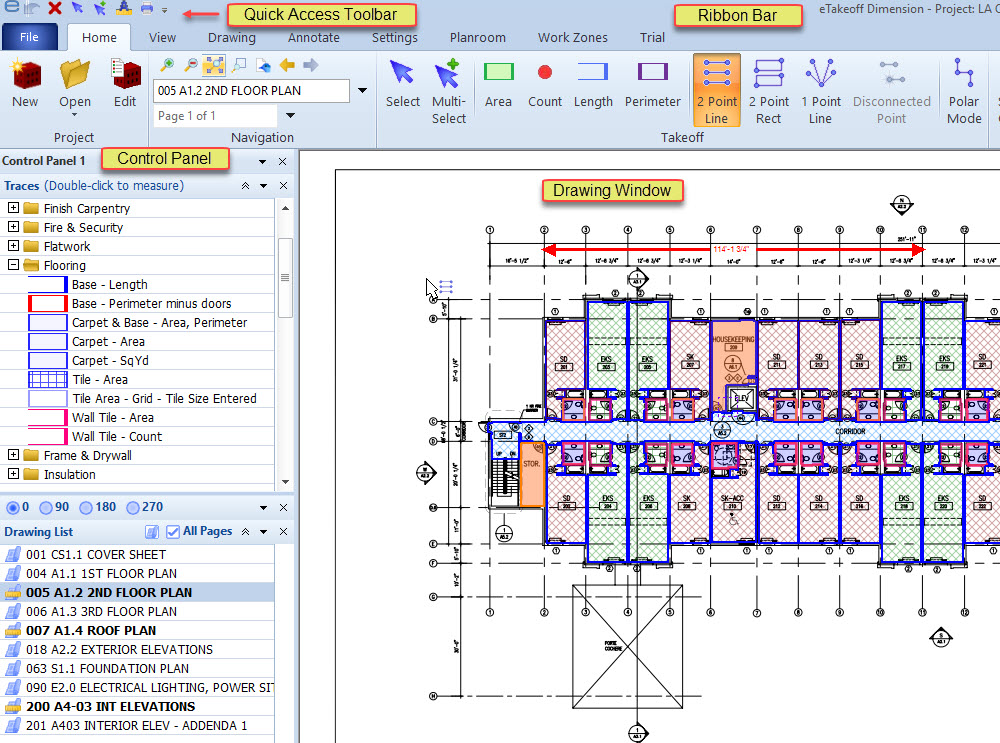
Figure 1: The Dimension Main Window
Figure 1 shows the main window for Dimension. This window is always visible, even though other windows may be partially overlap it.
The Drawing Window -
In the center of the main window is the drawing window. This displays
the current drawing plus any measurements, and annotations. In figure
1, the entire drawing is shown in the drawing window. You can zoom and
scroll to see more detail.
Is your Drawing Window Blank?
It will be the first time you start Dimension. It means you don't have
a current drawing. You can load a drawing in several ways:
- If you have previously downloaded drawings files, Use the Home Tab's New Project button to create a Dimension Project for the drawings
- See Getting Started for instructions on loading the sample project.
Ribbon Bar, Quick Access Toolbar & Control Panels
The Ribbon Bar - At the top of the main window is the Ribbon Bar The ribbon bar has different tabs organized for different modes of operation. The ribbon bar has extensive tool tip capability. You can hover the mouse over any button to display its tool tip.
The Quick Access Toolbar - The Quick Access Toolbar can be customized to make frequently used commands available no matter which tab is displayed.
Control Panels - Control Panel are vertical panels that can be displayed docked on the sides of the Main Window or floated above or beside the window. Different "Controls" can be placed in a panel to provide quick access to functions that are normally accessed via multiple mouse clicks.
Cursors
Different cursors are displayed in the main window to indicate the current mouse mode (what will happen when you click or release the mouse).
Keyboard Shortcuts and Context Menu Options
Keyboard Shortcuts
Backspace or Ctrl/Z - Pressing the Backspace key has the same effect as pressing the Undo button on the Ribbon Bar Home Tab It reverses the last editing step.
Delete - Pressing the Delete key (while the Shift key is up) deletes the selected measurements and annotations. If nothing is selected, it will delete the current drawing from the project. Before deleting, you will be asked if you're sure you wish to delete the measurements and annotations or the drawing.
Shift/Delete - Pressing the Delete key
while the Shift key is down deletes the
selected measurements and annotations. If nothing is selected, it will
delete the current drawing from the project.
Warning: With the Shift key down, the delete will
take place immediately. You will not be asked if
you are sure.
Enter - Pressing the Enter key has the same effect as pressing the Select Measurement on the Ribbon Bar Tab or the Annotation Ribbon bar Tab. You can then click on a measurement or annotation to select it.
Escape - Pressing the Escape key has the same effect as pressing the Cancel button on the Ribbon Bar Tab. It cancels all changes made to the measurements or annotations you're working on.
Page Down - Pressing the Page Down key displays the next drawing for the project.
Page Up - Pressing the Page Up key displays the previous drawing file for the project.
Down Arrow - Pressing the Down Arrow key causes the drawing to scroll down one screen. In multi-page drawing files, if the bottom of the current page is already displayed, or if the Shift key is down when the Down Arrow key is pressed, the next page of the drawing will be displayed.
Up Arrow - Pressing the Up Arrow key causes the drawing to scroll up one screen. In multi-page drawing files, if the top of the current page is already displayed, or if the Shift key is down when the Up Arrow key is pressed, the previous page of the drawing will be displayed.
Left Arrow - Pressing the Left Arrow key displays the previously viewed drawing within the current project. It behaves the same way as pressing the Previous button in the Ribbon Bar Home Tab.
Right Arrow - After you use the Left Arrow key or the Previous button to go back one or more steps, you can go forward again by pressing this key. Navigating by any other method eliminates the "forward" history and the key will have no effect. It behaves the same way as pressing the Next button in the Ribbon Bar Home Tab.
Ctrl - When adding or moving points for measurements, line annotations or cloud annotations, you can hold down the "Ctrl" key while clicking or dragging to toggle Polar Mode.
Shift - When adding or points for measurements, you can hold down the "Shift" key while clicking to make the point "Uncounted". Uncounted points are only supported in the Premier viewer.
A - Pressing the "A" key has the same effect as pressing the Add Points to Measurement button on the Ribbon Bar. In this mode, each time you click on the drawing, the point is added to the current measurement.
C - Pressing the "C" key has the same effect as selecting "Create Arc" from the Context Menu. The last three points will be converted into an arc as described in Taking off Arcs and Circles.
D - Pressing the "D" key has the same effect as selecting "Edit Description..." from the Context Menu. The Description Edit Window will be displayed, allowing you to set the description for the selected measurements and/or annotations.
E - Pressing the "E" key has the same effect as pressing the Edit Points Button On the Home Ribbon Bar or the Annotation Ribbon Bar. In this mode, you can move points, insert points or delete points.
F - Pressing the "F" key has the same effect as selecting the Drawing/Zoom Full Size from the Home Ribbon Bar. The entire drawing is displayed in the main window.
G - Pressing the "G" key has the same effect as pressing the Add Disconnected Point button on the Home Ribbon Bar. The next time you click on the drawing, a disconnected point is added to the current measurement.
H - Pressing the "H" key toggles the crosshair display on/off. The crosshair settings are defined in the User Preferences Window under the "Drawing" tab.
I - Pressing the "I" key has the same effect as selecting "Create an Issue..." from the Context Menu. It creates a new issue for the selected measurements and annotations.
M - Pressing the "M" key has the same effect as pressing the Move/Copy Measurements and Annotations button on the Home Ribbon Bar.In this mode, you can move or copy the selected measurements and annotations by clicking down and dragging.
N - Pressing the "N" key starts a new measurement using the previously selected Trace.
O - Pressing the "O" key rotates the drawing 90 degrees clockwise from its current rotation
Shift/O - Pressing the "O" key while holding down the Shift key rotates the drawing 90 degrees counter-clockwise from its current rotation
P - Pressing the "P" key has the same effect as pressing the Polar Mode button on the Home Robbon Bar. When adding points in polar mode, the point is forced to fall on a line that is a multiple of 90 degrees from the previous point. This is most commonly used to create horizontal or vertical lines. It can also work for lines of various angles.
Q - Pressing the "Q" key has the same effect as selecting File/Print/Batch Print /Add Current Drawing to Queue" from the Ribbon Bar. The drawing currently displayed in the main window is added to the print queue. An "Exclamation" sound will be played to indicate that the drawing has been queued.
S - Pressing the "S" key has the same effect as pressing the Select Measurement or Annotation button on the Home Ribbon Bar or the Annotate Ribbon Bar. You can then click on a measurement or annotation to select it.
T - Pressing the "T" key has the same effect as selecting "Select Trace..." from the Context Menu. The Standard Trace Tree Window will be displayed. This will allow you to set the trace for the selected measurements.
Shift/T - Pressing the "T" key while holding down the Shift key has the same effect as selecting "Edit Trace..." from the Context Menu. if a single measurement is selected, the Trace Editing Window will be displayed allowing you to set the trace for the selected measurement. If multiple measurements are selected, the Trace Properties List Window will be displayed allowing you to change individual properties across multiple measurements.
W - Pressing the "W" key has the same effect as pressing the One-time Assignment button on the Worksheet Assignment Control It assigns the selected measurements and annotations to the item currently selected in the Worksheet Assignment Control List.
X - Pressing the "X" key has the same effect as selecting "Edit Extension..." from the Context Menu. The Extension Measurement Values Window will be displayed, allowing you to set the extension values for the selected measurement.
Z - Pressing the "Z" key has the same effect as selecting "Easy Trace Creation/Edit..." from the Context Menu. it displays the Easy Trace Creation/Edit Window. This window is used to easily edit a subset of the properties of a measurement trace and (optionally) create a matching standard trace.
2 - Pressing the "2" key has the same effect as pressing the Add 2 Point Lines button on the Home Ribbon Bar. As you click on the drawing, each two points will be added to the measurement as a disconnected line.
4 - Pressing the "4" key has the same effect as pressing the Add 2 Point Rectangles button on the Home Ribbon Bar. As you click on the drawing, each two points will be added to the measurement as a disconnected rectangle defined using the points as opposite corners.
F2 - Pressing the "F2" key has the same effect as selecting Rename Drawing Button from the Drawing Ribbon Bar. If the drawing is part of a single-page file, the drawing description will be changed (not the filename). If the drawing is part of a multi-page file, the description for the current page will be changed. For more information see The Drawing/Page Rename Window .
Context Menu
The Context Menu is displayed when you click the right button on the mouse. It is displayed where the mouse cursor is positioned on the screen. If you are in single select mode, pressing the right mouse button selects the measurement or annotation under the mouse cursor before displaying the context menu. If you have already selected the desired measurement or annotation, you must right-click on that measurement. In other modes, it doesn't matter where you right-click.
The actual menu options displayed and which are enabled will depend on what you're doing. Here are the possibilities:
- Undo the Last Operation - Select this option to undo the last change made to a measurement or annotation. You can select this option multiple times to undo multiple changes. Undo works on all changes made when adding or editing a measurement on annotation. Once you leave the measurement or annotation, the undo capability ends.
- Cancel All Work on Object - Select this option to cancel all changes to the object (measurement or annotation) you're working on. If you are adding a new object, it will be deleted. If you are making changes to an existing object, all changes made since you selected it will be reversed.
- Add New Measurement Using This Trace - This will only be displayed if you have selected a single measurement. Selecting this option starts a new measurement using the same parameters as the selected Measurement.
- Add Disconnected Point - Sometimes a
single measurement is desired for several separate lengths or areas.
Dimension handles this using "disconnected" points. The last point
of the first length or area is "disconnected" from the first point
of the next length or area.
To create two disconnected groups, first add the points in the first group, select this option, then add the first point of the second group. A measurement can have an unlimited number of groups.< - Create Arc - This will only be displayed if you are adding points to a measurement and have added at least 3 non-disconnected points. If you select this option, the last three points will be converted into an arc as described in Taking off Arcs and Circles.
- Copy Measurement - This will only be displayed if you are adding a measurement or have selected a single measurement. If you select this option, a sub-menu will be displayed allowing you to copy the Point Count, Length, Perimeter or Area for the current measurement to the System Clipboard. You can then switch to another application and Paste the measurement.
- Return to Estimating with Quantity - This will only be displayed if you have invoked Dimension from an estimating application that has been integrated with Dimension. In addition, you must be adding a measurement or have selected a single measurement. If you select this option, the quantities for the current measurement will be returned to the estimating application and you will be switched to that application.
- Edit Measurement Description... - This will only be displayed if you are adding or have selected one or more measurements or annotations. This option is not available in the Basic Viewer. If you select this option, the Description Edit Window will be displayed, allowing you to set the description for the selected measurements and/or annotations.
- Edit Measurement Trace... - This will only be displayed if you are adding or have selected one or more measurements. This option is not available in the Basic Viewer. If you select this option with a sinlge measurement selected, the Trace Editing Window will be displayed, allowing you to set the trace for the selected measurement. If multiple measurements are selected, the Trace Properties List Window will be displayed allowing you to change individual properties across multiple measurements.
- Change Trace... - This will only be displayed if you are adding or have selected one or more measurements. If you select this option, the Standard Trace Tree Window will be displayed. This will allow you to set the trace for the selected measurements.
- Select all measurements using this Trace - This will only be displayed if you have selected a single measurement. Selecting this option will select all measurements using the same Trace on the drawing page.
- Easy Trace Creation/Edit... - If you select this option, the Easy Trace Creation/Edit Window will be displayed. This window is used to easily edit a subset of the properties of a measurement trace and (optionally) create a matching standard trace.
- Edit Extension... - This will only be
displayed if you are adding or have selected a measurement whose
trace uses an extension. For more information see the Extensions
Overview. If you select this option, the Extension
Measurement Values Window will be displayed, allowing you to
set the extension values for the selected measurement. If the
measurement uses a grid or roll
extension, a sub-menu will be displayed:
- Edit Extension Values... - This option will edit the extension values as described above.
- Move/Rotate Layout... - This option will display the Move/Rotate Toolbar allowing you to move the grid orientation or rotate it. For more information see Editing a Measurement's Grid Information or Editing a Measurement's Roll Information.
- Change Color... - This will only be displayed if you are adding or have selected one or more annotations. This option is not available in the Basic Viewer. If you select this option, the Windows Standard Color Selection Dialog will be displayed, allowing you to pick a text/foreground color for the selected annotations.
- Change Background Color... - This will only be displayed if you are adding or have selected one or more annotations that use a background color. This option is not available in the Basic Viewer. If you select this option, the Windows Standard Color Selection Dialog will be displayed, allowing you to pick a background color for the selected annotations.
- Change Text Font... - This will only be displayed if you are adding or have selected one or more text annotations. This option is not available in the Basic Viewer. If you select this option, the Windows Standard Font Selection Dialog will be displayed, allowing you to pick a font for the selected annotations.
- Zoom Font Size - This will only be
displayed if you are adding or have selected a single text
annotation. This option is not available in the Basic Viewer. If
dynamic font sizing is currently on for the annotation, a check mark
will appear before this option. If you select this option, the
dynamic font will be toggled for the annotation.
When sizing is off, the text is always displayed in the selected font size, no matter how much the drawing is zoomed in or out.
When sizing is on, the font size changes as you zoom. When the drawing is displayed in its original size, the text will be displayed in the selected font size. As you zoom in or out, the font is proportionally larger or smaller. - {quantity worksheet assignments} -
These options will only be displayed if you are adding or have
selected a single measurement or annotation that is assigned to the
Quantity Worksheet. This option is not
available in the Basic Viewer. One entry will be displayed for each
Quantity Worksheet Item that the measurement or annotation is
assigned to. The actual menu text will be the breakdown code and
description of the item. If you select one of these options, a
sub-menu will be displayed.
The first entry in the sub-menu will be "Show in Quantity Worksheet". If you pick that sub-option, the Quantity Worksheet will be displayed with the focus on the selected measurement or annotation assignment. If there are other measurements or annotations assigned to the same worksheet item, they will be displayed as additional options in the sub-menu. If you select one of these sub-options, the drawing for the selected measurement/annotation will be displayed with the measurement/annotation selected. - Assign to {quantity worksheet item description} - This option will only be displayed if you are adding or have selected a single measurement or annotation while an item has been selected in the Worksheet Assignment Control panel. If you select this option, the selected measurement or annotation will be assigned to the toolbar item.
- Delete {measurement/annotation description} - This option will only be displayed if you are adding or have selected a single measurement or annotation; This option is not available in the Basic Viewer. If you select this option, the selected measurement/annotation will be deleted. If you select this while holding the Shift key down, it will be deleted immediately. Otherwise you will be asked if you're sure you want to delete.
- Delete XX measurements and/or annotations - This option will only be displayed if you have selected multiple measurements and/or annotations; This option is not available in the Basic Viewer. If you select this option, the selected measurements and/or annotations will be deleted. If you select this while holding the Shift key down, they will be deleted immediately. Otherwise you will be asked if you're sure you want to delete.
- Merge XX selected measurements into one -
This option will only be displayed if you have selected multiple
non-multi-page measurements and right-click on one of them. If you
select this option, all the selected measurements will be merged
into the measurement you right-clicked on.
Warning: There is no Undo for the merge operation. - Delete Point # - This option will be displayed when you right click next to a measurement point. If you select this option, the point will be deleted.
- Point # Uncounted - This option will be displayed when you right click next to a measurement point. If the point is currently uncounted, this menu option will be checked. If you select this option, the point will be toggled from counted to uncounted or vice versa. Uncounted points are excluded from the Count quantity.
- Continue measurement on another drawing - This option will be displayed when you are adding or editing a measurement. After you select this option, switch to the desired drawing and select "Add New Measurement" from the measurement toolbar. The new points will part of the measurement originally selected. This option is only available with the Premier Viewer.
- Display Angle and Pitch... - To display the angles and pitches for the lines connected to a point, right-click on the point and select this option. The Angle and Pitch Window will be displayed. This option will only be displayed when in single selection mode and is not available in the Basic Viewer.
- Create an Issue... - This option will only be displayed if you have selected measurements and/or annotations that are part of a project; This option is not available in the Basic Viewer. If you select this option, The Issue Edit Window will be displayed to create an issue with the selected measurements an/or annotations assigned to it. For more information see Issues Overview.
- Existing Issues - When a single measurement or annotation is selected that is referenced by one or more issues, this option will be displayed. If you select this option, a sub-menu of issue descriptions will be displayed. You can click on any issue to view and/or edit it in the Issue Edit Window.
- Select from List... - This option will only be displayed when you are in single selection mode. It is useful when multiple measurements or annotations are overlaid it is difficult to select an individual measurement just using the mouse cursor. If you select this option, the Measurement Selection Window will display a list of the measurements and annotations that are close to the mouse cursor. From this list you can select a single measurement or annotation.
- Drawing Comparison - This option will only be displayed while you are comparing two drawings. This option is not available in the Basic Viewer. If you select this option, the Drawing Comparison Context Sub-menu will be displayed.
- Advanced Editing - This option
displays a sub-menu of advanced editing options. These options are
not available in the Basic viewer.
- Create cutout measurement from group X (points N-M) - This sub-menu option is displayed when you right-click on a cutout in a selected measurement. A cutout is a group of disconnected points that are digitized in a counter-clockwise direction so that the group area is excluded from the overall measurement area. If you select this option, a new measurement will be created that has the same points as the cutout group, but digitized in a clockwise direction. The Trace Tree will be displayed to select a trace for the new measurement. Cutout measurements are useful in flooring where a central part of a surface is covered with a different material.
- Delete all points in group X (points N-M) - This sub-menu option is displayed when you right-click on a group of disconnected points in the selected measurement. If you select this option, the group of points will be deleted from the selected measurement.
- Split off group X (points N-M) into a new measurement - This sub-menu option is displayed when you right-click on a group of disconnected points in the selected measurement. If you select this option, the group of points will be split off into a separate measurement.
- Split off all points in groups X-Y (points N-M) into a new measurement - This sub-menu option is displayed when you right-click on a group of disconnected points in the selected measurement. If you select this option, all points in the selected group and any subsequent groups will be split off into a separate measurement.
- Flip/Rotate Measurements - In some
estimating environments such as hotels or office buildings, a row of
rooms or other objects may be repeated on opposite sides of a hall.
It can save time to takeoff one side of the hall, then copy, move
and flip the takeoff to do the second side. The flip/rotate options
can be used to do this.
This option is displayed in Select or Multi-Select mode with measurements selected. Selecting this option displays a sub-menu of options.- Flip Horizontally
- Flip Vertically
- Rotate 90 Degrees
- Rotate 180 Degrees
- Rotate 270 Degrees
- Reverse Point Order
Reversing the point order is useful if you have digitized an area in a counterclockwise direction making it a negative area. Reversing the point order will make it a positive area.
These options are only available in the Advanced and Premier viewers. - Edit Not to Scale Lengths - Drawing scales (and detail scales) can be set to "Not to Scale". In this case the measurement length must be entered manually. Select this option to enter the lengths. For more information see Not to Scale Drawings.
- Generate Dimension Annotations -
This option allows you to automatically generate dimension
annotations for the overall dimensions of any selected measurements.
Selecting this option displays a sub-menu of options.
- Horizontal - Create a dimension annotation for the overall width of the measurement.
- Vertical - Create a dimension annotation for the overall height of the measurement.
- Horizontal and Vertical - Create dimension annotations for the overall width and height of the measurement.
- Parallel to Segment X - Create a dimension annotation for the overall size of the measurement on a line parallel to the segment.
- Parallel and Perpendicular to Segment X - Create dimension annotations for the overall size of the measurement on a lines parallel and perpendicular to the segment.