
Easy Trace Creation/Edit Window
Traces define the colors and other characteristics used to display measurements. There are standard traces, measurement traces and quantity worksheet traces. The Easy Trace Creation/Edit Window is used to easily edit a subset of the properties of a measurement trace and (optionally) create a matching standard trace.
This window is most useful when initially building a library of standard traces. When you need to measure something new (with no standard trace), start with a similar standard trace, invoke this window, modify the trace as needed then save it as a standard trace.
This window only has a subset of all the properties of a trace. If you need to modify the other properties you should use the Trace Properties Window.
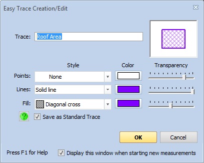
Figure 1: The Easy Trace Creation/Edit Window
This window can be invoked by selecting an existing measurement or starting a new measurement then selecting "Easy Trace Creation/Edit" from the context menu or pressing the "Z" shortcut key.
Trace - When initially displayed, this will be the name (description) from the trace you started with (typically a standard trace). If you want to create a new standard trace it must have a different name.
The primary use of trace names in when selecting standard traces from the Standard Trace Tree Window or the Trace List/Tree Control. Each standard trace must have a unique name.
Note: This is the description for the trace. The measurement can have a different description. You might have a trace description "Hard Wood Flooring" and a measurement trace of "Dining Room Flooring".
When editing the trace for a measurement, this description is used to combine measurements in the Drawing Legend. To edit the description of the measurement itself, right-click on the measurement and select "Edit Description" from the Context Menu.
Preview Window - The preview window shows what the trace will look like on a simple four point measurement. As you change the characteristics, the preview window will be instantly updated to show the resulting look.
Display Characteristics
Traces have three sets of display characteristics. The characteristics include "Style", "Color" and "Transparency". The "Point" characteristics are used to display a symbol at each point of the measurement. The "Line" characteristics are used to draw the lines between the points. The "Fill" characteristics are used to fill the inside of the polygon defined by the points.
Style - For Points, you can select from a list of different symbols that can be displayed at each point. For Lines you can select from a line style list that includes none, solid, dotted, dashed, etc. For Fill you can select from a list of different fill patterns.
Color - Press this button to select the color to be used for the points, lines or fill.
Transparency - This slider controls the transparency of the display. Move it to the left for more transparency, to the right for less. More transparency means you can more clearly see the drawing behind the trace.
Save as Standard Trace - This checkbox will be displayed left of the "OK" button when editing a measurement trace. If it is checked (the default), the measurement trace will be saved as a standard trace.
NOTE: If you organize traces in a tree, the new standard trace will be saved in the root folder of the tree.
There is a help button to the left of this checkbox. If you press it you will see an extended explanation of the checkbox.
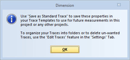
Figure 2: Save as Standard Trace Help Window
OK - Press this button to finish defining the trace and save the trace properties.
Cancel - Press this button to cancel trace definition and discard all changes.
Display this window when starting new measurements - if you check this box, the Easy Trace Edit Window will be displayed whenever you start a new measurement.