
User Preferences Window
This window is used to set various user preferences. It is invoked from the Main Menu's "Admin/User Preferences..." option. There are eleven tabs at the top of the window. Pressing on different tabs allows you to set different kinds of preferences as described below.
Drawing Window Preferences
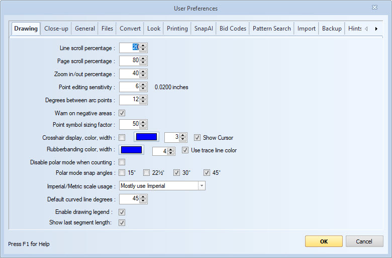
Figure 1: The User Preferences Window - Drawing Tab
These settings control the operation of the drawing window See Main Window.
Line scroll percentage - Set the percentage (of a page) that you want the drawing to scroll when pressing the up/down or right/left buttons at the ends of the scroll bars. Usually this will be 10% to 20%.
Page scroll percentage - Set the percentage (of a page) that you want the drawing to scroll when you click in the slide area of the scroll bar (but not on the slider itself). Usually this will be 80% to 100%.
Zoom in/out percentage - Select the percentage you want to scroll in or out when pressing the "Zoom In" or "Zoom Out" buttons on the Main Toolbar. Usually this will be 50%
Point editing sensitivity - This setting is used when selecting or editing points for measurements and annotations. If the point you click on is within this many pixels of a point, it will be considered clicking on that point. If you have difficulty clicking on points, increase this setting. If you find it difficult not clicking on a point, reduce this setting. The sensitivity distance in inches is shown to the right.
Degrees between arc points - This setting is used when automatically generating circle or arc points. See Taking off Arcs and Circles. A setting of 12 degrees (the default) will generate 30 points for a complete circle, creating a measurement within 2-3% of the actual arc. A smaller setting will generate more points and increase accuracy.
Warn on negative areas - Check this box if you want the Negative Area Warning Window to be displayed when digitizing a negative area. If you digitize an area in a counter-clockwise direction, the area is computed as a negative value. This allows cutout calculations.
The warning is useful for new users to remind them to digitize in the clockwise direction. It is only displayed when the area is negative and you select to display the "Total Area" or "Group Area" in the Measurement Quantities Control on the Measurement Toolbar.
This setting can also be turned off from the Negative Area Warning Window.
Point symbol sizing factor - Point symbols are the symbols and/or text displayed at each point of a measurement. They are defined as a part of the measurement's trace. This setting determines how the size of the symbol changes as you zoom in and out.
If the setting is zero, the symbol is always displayed at the size of a 10 point font, no matter how much you zoom in or out.
If the setting is one hundred, the symbol is displayed as though it was drawn on the drawing using a 10 point font. As you zoom in it gets larger, as you zoom out it gets smaller.
If the setting is somewhere in between, the size will change slightly for lower settings and more for higher settings.
Crosshair display, color and width - Check the box to display crosshairs in the drawing window when measuring. You can also select the color and width of the crosshair lines. The selected color will be drawn over white areas of the drawing with the opposite color drawn over black areas of the drawing. You can show or hide the cursor when the crosshairs are displayed. The crosshar display can be toggled on/off using the "H" shortcut key in the main window.
Rubberbanding color, width - You can select the color and width of the rubberbanding lines. These are the lines drawn from the previous point to the cursor when adding points to a measurement. The selected color will be drawn over white areas of the drawing with the opposite color drawn over black areas of the drawing. If you check "Use trace line color", the color will be the trace's line color when working with measurements.
Disable polar mode when counting - When adding points, polar mode causes a point to be placed on a line which is some multiple of 15 degrees from the previous point. This is most commonly used to force horizontal or vertical lines. When counting, this is of limited use and may even be undesirable. If you select this option, polar mode will be disabled when adding points to a measurement whose data type is "Count".
Polar mode snap angles - Check the various angle to which you wish to snap. Vertical and horizontal lines will always be snapped when polar mode is on. If this is all you want, don't check anything. For any checked angle, it will snap to that angle left or right of vertical and above or below horizontal.
Imperial/Metric Scale Usage - This setting determines how imperial (feet/inches) vs. metric scales are presented. Select from the following options:
- Always use Imperial - Metric scales will be omitted from scale lists
- Mostly use Imperial - Imperial scales will be listed first. Metric scales second
- Always use Metric - Imperial scales will be omitted from scale lists
- Mostly use Metric - Metric scales will be listed first. Imperial scales second
Default curved line degrees - During trace editing you can choose to curve the lines between points. This is the default curvature. During Advanced Point Editing you can drag the lines to the desired arc.
Enable Drawing Legend - Uncheck this box if you want to turn the drawing legend off for all Projects and the corresponding drawing pages.
Show last segment length - Check this box if you want to display lengths between points as measurements are taken off.
Close-up Window Preferences
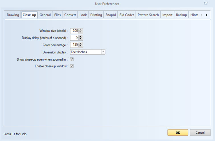
Figure 2: The User Preferences Window - Close-up Tab
These settings control the operation of the close-up window. The close-up window is displayed when you click down to set or select a point on a drawing. It shows a close up of the area under the mouse cursor.
Window size (pixels) - This is the size (height and width) of the close-up window in pixels. Most screens have 50 to 75 pixels per inch.
Display delay (tenths of a second) - This is the amount of time before the close-up window is displayed. When doing quick, easy clicks, the close-up window can be distracting. By setting a delay, the window doesn't appear on quick clicks. It only appears if you hold the mouse motionless (with a button down) for the specified time. If you set this to several seconds (20-20 tenths), it effectively disables the close-up window.
Zoom percentage - This is the zoom percentage used to display the drawing inside the close-up window. 100% means each pixel in the close-up window will represent 1 drawing pixel. 50% means each close-up window pixel will represent 4 drawing pixels (2 by 2).
Dimension display - You can optionally display line lengths in the close-up window when setting or moving measurement points. If there are multiple lines attached to the point, each line will and length will be shown in a unique color as shown in figure 3:
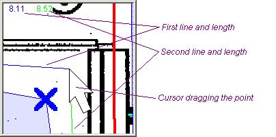
Figure 3: Close-up Window with Lengths Displayed
The Dimension display can be set to any of the following:
- None - Dimensions will not be displayed
- Decimal - Dimensions will be displayed with decimal notation (5.25)
- Feet/Inches - Dimensions will be displayed with foot/inch notation (5-3)
Show close-up even when zoomed in - If this is NOT checked, the close-up window will only be displayed when the close-up window will show more detail. In other words, the drawing is zoomed in less than the close-up window zoom factor. This means that the dimension display (described above) is unavailable. If this IS checked, the close-up window will be displayed regardless of the drawing zoom.
Enable close-up window - This enables you to display the closeup window percentage used to display the drawing inside the close-up window.
General Preferences
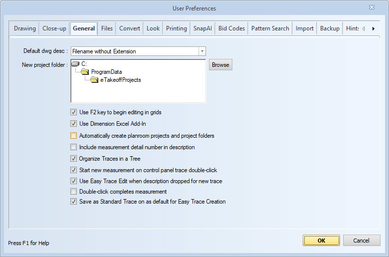
Figure 4: The User Preferences Window - General
Default dwg desc. -
Each drawing added to a Dimension project is given a description. These
descriptions appear in the drawing list in the
Project Toolbar Drawing List.
Clear descriptions allow you to quickly switch between drawings.
When a drawing is added, it is given a default description
based on the name of the drawing file.
we will use the following sample drawing file:
Dimension supports three different methods for generating default drawing descriptions.
- Filename without Extension -
The default description is the filename without the folder or the extension.
This is most useful when all drawings for a project are kept in a single
file and are given clear names. Consider the filename:
C:\DimensionProjects\LaQuinta Hotel\Cover Sheet.tif
The default description would be "Cover Sheet". - Filename with Folder Prefix -
The default description is the sub-folder plus the filename without the extension.
The sub-folder is all of the folders below the project folder.
This is most useful when drawings are divided into folders by division, building, etc.
Consider the filename:
C:\DimensionProjects\LaQuinta Hotel\Plan View.tif
Assuming the project folder is "C:\DimensionProjects\LaQuinta Hotel", the default drawing description would be "Landscaping\Plan View" - Filename with Folder Suffix -
The default description is the filename without extension
followed by the sub-folder.
The sub-folder is all of the folders below the project folder.
This is most useful when drawings care divided into folders by addenda.
Consider the filename:
C:\DimensionProjects\LaQuinta Hotel\Addenda\Plan View.tif
Assuming the project folder is "C:\DimensionProjects\LaQuinta Hotel", the default drawing description would be "Plan View Addenda"
New project folder - When adding a new project, the first step is to select the project folder. This preference defines where the folder selection dialog will start. To set this preference, press the "Browse" button and use the Dimension Folder Selection Window to select a folder.
Use F2 key to begin editing in grids - This applies to the Quantity Worksheet and the Measurement List. If this is checked, you can use the left/right arrow keys to move around the grid without interruption. If you wish to edit a cell, you can press the F2 key to begin editing its contents. If you wish to replace its contents, you can just begin typing. If this is NOT checked, you will begin editing as soon as the focus moves to an editable cell.
Use Dimension Excel Add-on -
Checking this box will add the Dimension Excel Add-in to the
Excel Add-in list.
Note: You must still select "Tools/Add-ins..." from
the Excel menu and check "Dimension".
Un-checking this box will remove the add-in
from Excel. That will break any existing spreadsheets that
use Dimension functions.
Automatically create planroom projects and project folders - This option only applies to information downloaded from an integrated planroom. Normally, when you save the first drawing file from a planroom project, the Project Setup Wizard is displayed. This allows you to edit the project information and options provided by the planroom before the project is created. If this option is selected, the project wizard is NOT displayed and the project and the project folder are created automatically.
Include measurement detail number in description - Each measurement that is part of a project has a sequential detail number. This number can be displayed and/or printed on the Measurement List and the Quantity Worksheet. Each measurement has an option to display the measurement description and/or quantity on the drawing. If this option is selected, the description is prefixed with the detail number. For example: "16.Slab on Grade; Area=123.45". This allows people using printed output to associate a measurement in the measurement list or quantity worksheet with the corresponding measurement on a drawing.
Organize Traces in a Tree - Checking this box will allow you to organize traces in a hierarchical tree and select them using that tree. For more information see Organizing Traces in a Tree.
Start new measurement on control panel trace double-click - With this option NOT selected, double-clicking on a control panel trace will assign the trace to any currently selected measurements. With this option selected, double-clicking on a trace in the control panel will start a new measurement using the selected trace. In either case, you can right-click on a control panel trace and select "Assign to selected measurements" from the context menu.
Use Easy Trace Edit when description dropped for new trace - New users often need to create many new traces to match their estimating system. If they have the names of those traces in an application such as Microsoft Word, they can easily create a new trace by dragging the description and dropping it on an existing trace that is similar to the one they want to create.
This can be done by dropping the description on a trace in the Control Panel Trace Tree Control or the Standard Trace Tree Window. When the drop is made, a trace edit window is displayed to create the new trace. Drops on the Standard Trace Tree Window always display the Standard Trace Edit Window. Drops on the control panel can display either the Standard Trace Edit Window or the Easy Trace Edit Window based on the setting of this check box.
Save as Standard Trace on as default for Easy Trace Creation - Checking this box will ensure that the "Save as Standard Trace" box is checked when creating new traces utilizing Easy Trace Creation/Edit Window to build new traces.
Files Preferences
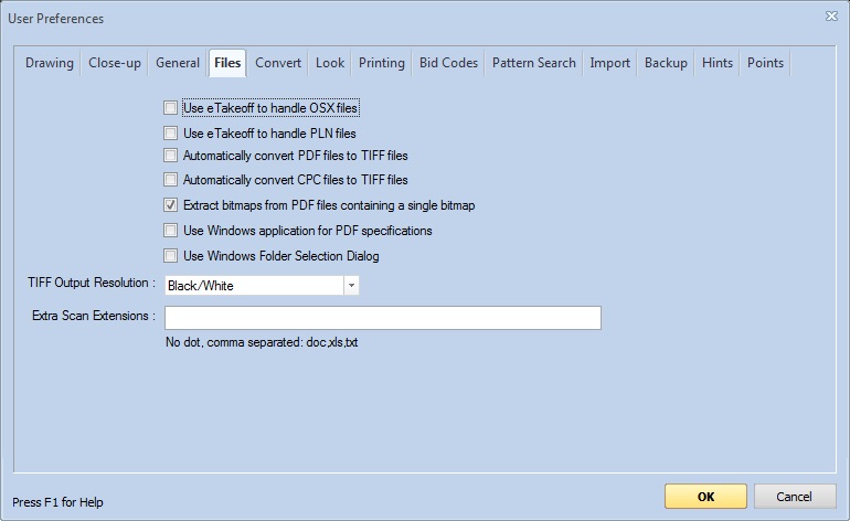
Figure 5: The User Preferences Window - Files
Use Dimension to handle OSX files - Some planrooms use OSX files to interface with On-Center's viewer. If you select this option, Dimension will intercept the OSX file and be integrated with the planroom. You should NOT select this option if you use the On-Center viewer.
Use Dimension to handle PLN files - Dodge Data & Analytics distributes drawings as files with the extension ".PLN" If you select this option, double-clicking on a PLN file will open the file in Dimension. You should NOT select this option if you use Dodge Data & Analytics's Dodge View viewer.
TIFF files have several advantages over other file types. They are very quick to display, zoom and scroll. In addition they are widely supported by software products when proprietary formats such as CPC are not.
Automatic conversion (when enabled) will convert files the first time they are viewed AND are part of a Dimension project. The converted TIFF file will have the same name as the original file but with the extension ".tif". The original file's extension will have "cvt" appended to it. So if the original file was named "CoverSheet.pdf", the converted file will be named "CoverSheet.tif" and the original file will be renamed to "CoverSheet.pdfcvt". Renaming the original file prevents it from being picked up during a subsequent scan for drawings.
Automatically convert PDF files to TIFF files - If this box is checked, PDF files will be automatically converted to TIFF files when first opened. Warning: TIFF files are bitmaps and will become pixilated (distorted) when zoomed in very closely. Most PDF files used for construction drawings are also bitmaps and suffer this same distortion. But some PDF files contain CAD commands and suffer no distortion. In this case, the PDF file may be preferable to the TIFF file.
Automatically convert CPC files to TIFF files - If this box is checked, CPC files will be automatically converted to TIFF files when first opened.
Extract bitmaps from PDF files containing a single bitmap - Drawings are frequently provided as PDF files containing a scanned image of the drawing (a bitmap). Extracting the bitmap allows it to be loaded, displayed and zoomed much more rapidly. Check this option to use bitmap extraction. If this option is checked, PDF files containing a single bitmap will NOT be automatically converted to TIFF files because there is no performance advantage.
WARNING: The extracted bitmaps may have a different resolution than the original PDF file. That means that any measurements made on the original PDF file may need to be re-done. If the original bitmaps were converted to TIFF files, there will be no problem.
This option will be checked on all new installations and it will be disabled so that it can't be un-checked. This avoids the resolution problem described above. If you need to un-check this option, click on one of the other tabs of the preferences window. Then hold the Shift key down while clicking on the "Conversion" tab. The option will be enabled.
Use Windows application for PDF specifications - If this box is checked, specifications files with the extension ".pdf" will be passed to Windows when they are opened. Windows will open them using the application assigned to PDF files (typically Adobe Reader).
You can identify a file as a specifications file in the Drawing Properties Window or the Drawing List Window.
Use Windows Folder Selection Dialog - If this box is checked, folders will be selected using the Windows Folder Selection Dialog rather than the Dimension folder selection dialog.
TIFF Output Resolution - When converting to TIFF (or saving as TIFF), there are four output resolutions available:
- Black/White - This produces the smallest TIFF file and takes the least amount of time for the conversion. But the file can be more difficult to read. It also has the disadvantage that any gray on the drawing will be converted to either black or white depending on how dark it is.
- 16 Level Gray-scale - This produces a larger file (typically four times larger but it can be as much as ten times larger) and takes longer to create than Black/White. In the file each pixel is one of 16 levels of gray varying from black to white. The file is much easier to read than Black/White.
- 256 Level Gray-scale - This produces an even larger file. In the file each pixel is one of 256 levels of gray varying from black to white. This is seldom more readable then 16 level gray-scale and usually doesn't justify the increased file size and longer creation time.
- Black/White with Dithering - This is similar to Black/White except that gray areas are "dithered". That means they are replace with a scattering of black and white pixels. When zoomed out it looks like the original gray but if you zoom in you will see the scattered pixels.
16 Level Gray-scale is the recommended setting. Some users prefer Black/White with or without dithering. 256 Level Gray Scale is rarely worth the increased storage requirements and increased conversion and display times.
Extra Scan Extensions - When scanning folders to find drawings, normally we just look for files that can be opened by Dimension. But you may wish to include other documents in the project (such as spreadsheets or Word documents). To include them, enter the extensions for the file types you want to include in this edit control. Extensions should be entered without the leading dot. Multiple extensions should be separated with commas.
When you scan for drawings, any files found with the specified extensions will be added to the list of files to be added to the project. If you add the files, they will appear in the drawing lists and trees. If you select them, they will be opened outside of Dimension in application associated with the file type. The files can (optionally) be included when you backup and zip a project.
WARNING: When you delete a project and elect to "Delete all files and folders for this project", these files will ALSO be deleted.
This option is NOT available in the Basic viewer.
Convert Preferences
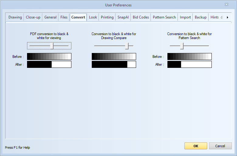
Figure 6: The User Preferences Window - Convert
There are four situations when we need to convert images from multi-color images to black and white images:
- When PDF files are converted to or saved as TIFF files and the user preference for TIFF conversion is Black/White
- When images are converted for Pattern Search
- When images are converted for Drawing Compare
- Zoom - Roll the mouse wheel forward to zoom in and backward to zoom out.
- Scroll/Pan - Hold down the left and right mouse buttons and move the mouse to scroll/pan.
- Black/White - This produces the smallest TIFF file and takes the least amount of time for the conversion. But the file can be more difficult to read.
- 16 Level Gray-scale - This produces a larger file (as much as ten times larger) and takes longer to create than Black/White. In the file each pixel is one of 16 levels of gray varying from black to white. The file is much easier to read than Black/White.
- 256 Level Gray-scale - This produces an even larger file In the file each pixel is one of 256 levels of gray varying from black to white. This is seldom more readable then 16 level gray-scale and usually doesn't justify the increased file size and longer creation time.
- None - Don't display any initial window.
- Select Files - Display the Windows File Open Dialog to select individual files.
- Select Folder - Select a folder that will be scanned for drawing files.
- Scan Drawings - Import drawings from a scanner.
- Existing Drawings - Rename drawings that are already part of the project.
During the conversion, colors other than black and white must be converted to either black or white. How this is done is specified separately for the four cases above.
As shown in Figure 6, each case has a slider bar, a "Before" image and an "After" image. The Before image shows the different levels of gray that might be found in a drawing. (Other colors are converted to an equivalent shade of gray before the gray-to-black/white conversion.) The After image shows whether the gray shade above it will be converted to black or white.
As you move the slider to the left, darker and darker shades of gray will be converted to white. As you move the slider to the right, lighter and lighter shades of gray will be converted to black.
Look Preferences
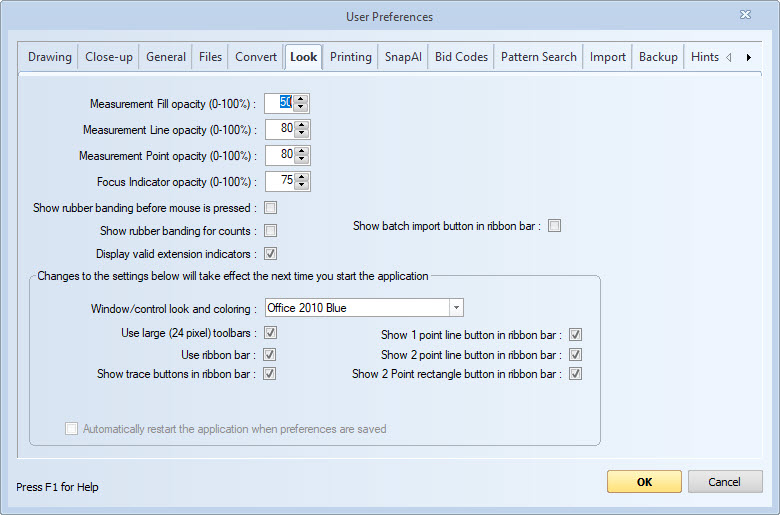
Figure 7: The User Preferences Window - Look
Opacity determines to what extent you can see the drawing through the measurement fill, lines, point markers and focus indicators. Opacity of 0% makes the measurement mark invisible. Opacity of 100% means the drawing can't be seen at all through the mark. These default opacity settings can be overridden on individual traces.
Measurement Fill opacity (0-100%) - The fill is painted over the entire inside of the measurement so the significant transparency is desired. Opacity of 50% is recommended.
Measurement Line opacity (0-100%) - This determines the opacity of lines drawn between points. A high opacity will make the lines more visible but 100% opacity would obscure the drawing lines beneath the measurement lines. Opacity of 80% is recommended.
Measurement Point opacity (0-100%) - This determines the opacity of symbols drawn at each point. 100% opacity would hide the corners. Opacity of 80% is recommended.
Focus Indicator opacity (0-100%) - This determines the opacity of the yellow circles drawn at each point of a measurement when it is selected.
Show rubber banding before mouse is pressed - When adding points, "rubber band" lines are drawn from the previous point to the point being added. Normally these lines are only drawn when the mouse is help down. If you check this box they will be drawn at all times.
Show rubber banding for counts - If this is NOT checked, the rubber banding will NOT be displayed when digitizing measurements whose first trace data type is Count. (The line and distance from one point to the next is typically not important.) But for some count takeoffs, the distance between the points IS important. If this box is checked, the rubber banding WILL be displayed for count takeoffs and the distance from the previous point will be displayed in the close-up window.
Display valid extension indicator - Measurements that use extensions have additional variables to be entered in addition to digitizing the points. For example, the extension "Overall Length" has input variables "Adder Count" and "Adder Length" If this box is checked, a blue "e" will be displayed next to the first point when the measurement is selected. This is a reminder to review the additional variable values.
If one of the variable values is missing, a red "e" will be displayed beside the first point, even if the measurement is NOT selected. The red "e" can't be turned off.
Changes to the preferences below will take effect the next time Dimension starts. If you change one of them, the option to automatically restart Dimension will be checked.
Window/control look and Coloring - Dimension supports several color themes that match themes found in Microsoft Office 2007 and 2010 (Blue, Black and Silver).
Use large (24 pixel) toolbars - On high resolution monitors, 16 by 16 pixel toolbar buttons can be difficult to see. Check this option to use larger (24 by 24 pixel) toolbar buttons.
Use ribbon bar - The ribbon bar provides a user-friendly interface for new users. It has larger button with descriptions and enhanced tool tips. As a result, commands are organized in multiple tabs. Experienced users familiar with the command buttons may prefer the traditional manu and toolbars.
Show trace buttons in ribbon bar - If this is checked, the Home tab of the ribbon bar will include four buttons to start new Count, Length, Area or Perimeter measurements. This are handy for users unfamiliar with the Trace control in the Control Panel. Once you start using the control panel, uncheck this option and the three buttons will be replaced by a single "New Measurement" button.
Show 1 point line button in ribbon bar - If this is checked, the Home tab of the ribbon bar will include a button to create one point lines
Show 2 point line button in ribbon bar - If this is checked, the Home tab of the ribbon bar will include a button to create two point lines
Show 2 point rectangle button in ribbon bar - If this is checked, the Home tab of the ribbon bar will include a button to create two point rectangles
Printing Preferences
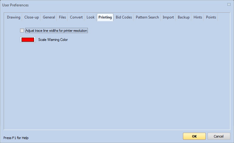
Figure 8: The User Preferences Window - Printing
Adjust trace line widths for printer resolution - If this box is checked, Line widths for traces will be adjusted to be the approximately the same size as they appear on the screen. Computer screens typically have a resolution of 50 to 100 dots per inch. Printers have resolutions of up to 1200 dots per inch. So a line that was one dot wide on the screen would be adjusted to be 5 to 20 dots wide when printed. Line width adjustment will also be done when traces are printed as icons in the Legend, the Measurement List and the Quantity Worksheet.
Scale Warning Color - This button displays the color of the scale warning which is optionally printed when a drawing is printed at a scale other than the original scale. Press the button to change the color.
Bid Code Preferences
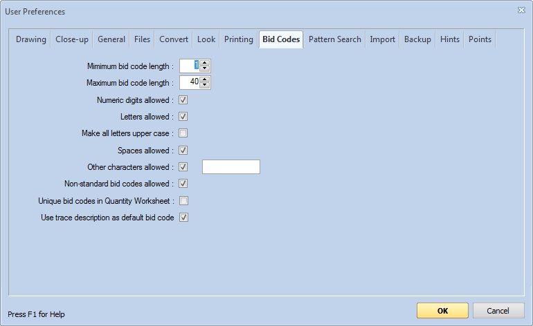
Figure 9: The User Preferences Window - Bid Codes
Minimum bid code length - Enter the minimum number of characters in a valid bid code.
Maximum bid code length - Enter the maximum number of characters in a valid bid code (up to 40).
Numeric digits allowed - Check this box if bid codes may contain numeric characters (0-9).
Letters allowed - Check this box if bid codes may contain the letters A to Z. This will allow both upper and lower case letters.
Make all letters upper case - Check this if all lower case letters should be converted to upper case.
Spaces allowed - Check this box if bid codes may contain spaces.
Other characters allowed - Check this box if bid codes may contain characters other than numbers, letters and spaces. If you want to limit bid codes to a SPECIFIC set of special characters, enter the allowed characters in the edit control to the right. If the edit control is empty, all other characters will be allowed.
Non-standard bid codes allowed - Check this box to allow users to specify bid codes for traces and quantity worksheet items that are NOT defined in the standard bid codes. If this isn't checked, bid codes must be defined in the standard bid codes before they are used in traces or quantity worksheet items.
Unique bid codes in Quantity Worksheet - If this is checked, no two quantity worksheet items within a project may have the same bid code.
Use trace description as default bid code - If this is checked, the trace description will be used for the bid code if no bid code is specified for the trace. This default bid code will be used in Excel measurement bid code formulas and will be displayed in the bid code columns in the measurement list. If you generally use a unique bid code for each trace, check this and you will only have to create bid codes when multiple traces share a common bid code.
Selecting this option will NOT change the way quantity worksheet bid codes work.
Pattern Search Preferences
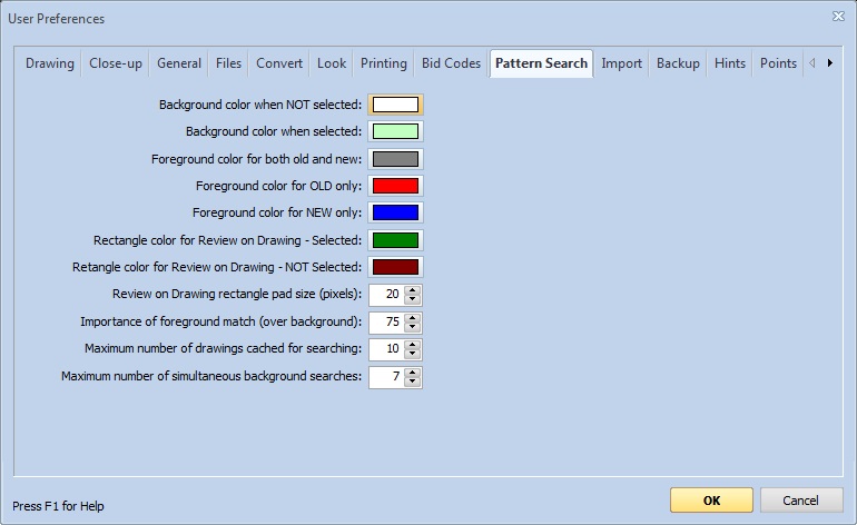
Figure 10: The User Preferences Window - Pattern Search
To understand these setting, you may wish to read the Pattern Search Overview. When a pattern search is complete, the results are displayed in a grid of thumbnail images. The best matches are at the top of the grid and the worst at the bottom. Patterns meeting a specified match quality are automatically selected. You can manually select or de-select individual patterns. Selected patterns can be idenfitied because they have a different background color.
Background color when NOT selected: - Press the color button to select the background color for patterns that are NOT selected.
Background color when selected: - Press the color button to select the background color for patterns that ARE selected.
Selected patterns can be displayed in "comparison" mode. In this mode. Areas that are white in both the desired pattern and the found pattern are displayed in one of the background colors defined above. Colors can be defined for areas that are black only in the desired pattern (the OLD pattern), only in the found pattern (the NEW pattern) and in both patterns.
Foreground color for both old and new: - This is the color for areas that are black in both the desired pattern and the found pattern. Typically this is a black or dark gray color.
Foreground color for OLD only: - This is the color for areas that are black in the desired pattern but white in the found pattern.
Foreground color for NEW only: - This is the color for areas that are white in the desired pattern but black in the found pattern.
Rectangle color for Review on Drawing - Selected: - During Review on Drawing, this color is used to draw a rectangle around matches that ARE selected.
Rectangle color for Review on Drawing - NOT Selected: - During Review on Drawing, this color is used to draw a rectangle around matches that are NOT selected.
Importance of foreground match (over background): - Found patterns will frequently have additional lines drawn over them that are not found in the desired pattern. Having these "background" mismatches are usually less significant than having areas that are in the desired pattern but not in the found pattern ("foreground" mismatches). You can emphasize the importance of foreground matches over background matches. This is a setting (0-100) for the percentage of the match quality that will be based on the foreground match. For setting of 75%, this would mean that the overall match quality would be based 75% on the foreground match and 25% on the background match.
Maximum number of drawings cached for searching: - Drawings frequenty need to be converted into a searchable format. This is done when the initial search is done and again during the review. The conversion can take up to a minute or more depending on the size and resolution of the drawing.
If you cache the converted drawing, the re-converting won't be needed for review or for subsequent searches for another pattern. But each cached drawing can use up to 5MB of memory. Set the maximum to a number that will not cause you to run low on memory. You can use the Window's Task Manager to see how much memory you have and how much is typically used. If you had 500 MB of spare memory, you could cache up to 100 files. If you see overall performance decline, you should lower this number.
Maximum number of simultaneous background searches: - You can now do multiple searches in the background while doing other work. If your computer has multiple processors, you can do multiple searches simultaneously. Set this to the number of processors you have minus one.
SnapAI Preferences
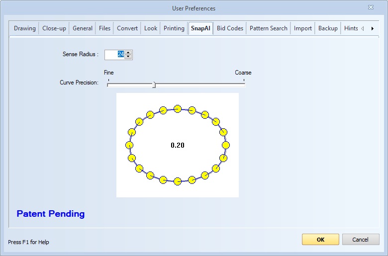
Figure 16: The User Preferences Window - SnapAI Tab
Sense Radius - This setting is used for the sense indicator shown during Snap. Increasing the sense radius will enlarge the sense indicator circle as well as increase the sensing area. Decreasing the sense radius will reduce the size of the sense indicator circle as well as reduce the size of the sensing area.
Curve Precision - This setting is used when Snap Line or Snap Polyline have curves in the detected line. As the user moves the slider from Fine to Coarse, the amount of points in the curve found decreases which affects the accuracy of the measurement. Fine is most accurate. Coarse is less accurate.
Backup Preferences
Projects can be configured for Auto-Backup. When auto-backup is set for a project, each time you change that project and leave it, it is automatically backed up to save all the project information (but not the drawing files). Auto-backup can be set in the Project Properties Window or the Project List Window.
Auto-backup has several purposes. If you keep your project database on a computer or in a folder that isn't backed up regularly, any disk problems or other computer problems may destroy your project database and all the project information. You can use auto-backup to save that information on a server or in a folder that is backed up.
Sometimes a group of users have independent project databases on their own computers, but share projects by backing them up to a common server. With auto-backup, the server automatically has the latest version of the project.
Sometimes we make mistakes. You may wish you could roll back your work on a project to some previous time. Auto-backup with "Separate Files by Day" option discussed below provides archive files you can roll back to.
The settings in this user preferences page determine the folder and filename used for the auto-backup output to meet your particular needs.
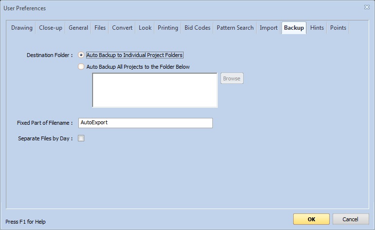
Figure 11: The User Preferences Window - Backup
Destination Folder - You can either auto-backup projects to their own individual project folders or back them all up to the same specified folder.
Select "Auto Backup to Individual Project Folders" when your project folders are stored on a server which is backed up and/or is used to share projects with other users.
Select "Auto Backup All Projects to the Folder Below" when you just want to put them somewhere that's easy to back up. If you select this option, press the "Browse" button to use the Dimension Folder Selection Window to select the desired folder.
Fixed Part of Filename -
The auto-backup filename is of the form:
[project description]-AutoExport-[project number].tpx
An example would be "LaQuinta Hotel-AutoExport-123.tpx".
The "AutoExport" part is considered the "fixed" part of the filename
because it doesn't change based on the project.
In the scenario where multiple users are doing auto-backup to a shared
folder, two users backing up the same project might overwrite each
other's backup. To avoid this, each user can change the fixed part
of the filename. We suggest you add your initials to the end so
you can easily see who backed up the project.
Separate Files by Day - Using just the file naming above, there is only one backup file (or one per user). But it might be useful to have a series of backup files for recent times. We partially accommodate this with the Separate Files by Day option.
If you select this option, the backup filename will include the name of the day of the week it was made. Using the example above for an backup file made on Wednesday, the filename would be "LaQuinta Hotel-AutoExport-123-Wed.tpx". This will provide a series of backups over the last week or so. For a project that's worked on every day, you would have five different backup files (seven if you work weekends). The oldest would be six days old.
WARNING: This technique is not foolproof. If you do all your takeoff on Mondays, there will only be one backup file.
Hint Window Preferences
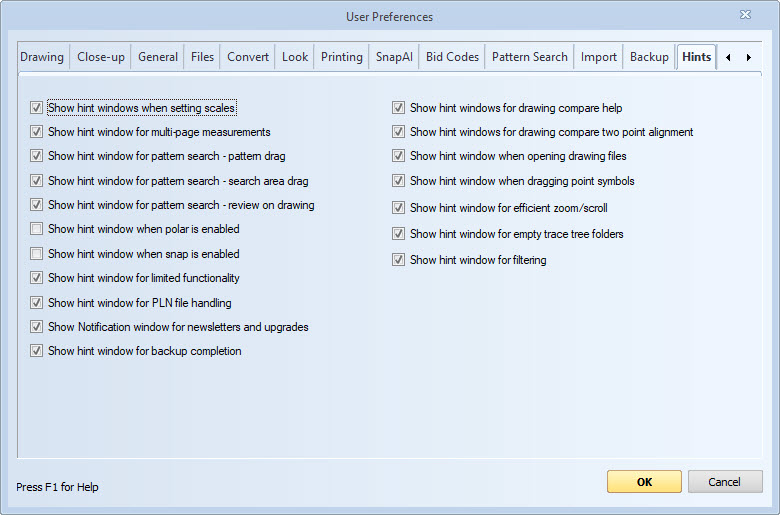
Figure 12: The User Preferences Window - Hint Windows
Hint windows are displayed to assist novice users when performing multi-step operations. Once users are familiar with the operations the hint windows may become a distraction. Most hint windows have a checkbox for display. This can be un-checked to eliminate the hint window. This user preference page can be user to turn the hint window back on.
Show hint windows when setting scales - Check this box to display hint windows when calibrating scales or setting the border for detail scales.
Show hint window for multi-page measurements - Check this box to display a hint window when continuing a measurement on another page.
Show hint window for pattern search - pattern drag - Check this box to display a hint window when dragging a rectangle around a desired search pattern.
Show hint window for pattern search - search area drag - Check this box to display a hint window when dragging a rectangle around the area you wish to search.
Show hint window for pattern search - review on drawing - Check this box to display a hint window when reviewing pattern search matches on the drawing.
Show hint window when polar is enabled - Check this box to display a hint window when polar mode is enabled. Polar mode is most commonly used to create horizontal or vertical lines, but it also works for lines of various angles. This hint window is intended for novice users who inadvertently turn on polar mode.Most experienced users will not want this hint.
Show hint window when Snap is enabled - Check this box to display a hint window when snap is enabled. The Snap Assistant hint box will appear while Snap is on during the takeoff of a measurement. Snap Assistant instructions will change accordingly as the user performs takeoff.
Show hint window for limited functionality - Starting with Dimension 3.0, Basic users are upgraded to Pro functionality when working with files from Dodge Data & Analytics. If you have never worked with files from Dodge, the hint will never be displayed. If you work with Dodge files, then work with non-Dodge files, many of the Pro menu options will be enabled for the non-Dodge files. When you invoke Pro functionality, the Limited Functionality Window will be displayed explaining that the functionality is only available with Dodge files. If you Un-check this option, the Pro menu options will be disabled when working with non-Dodge files.
Show hint window for PLN file handling - Dodge Data & Analytics distributes drawings as files with the extension ".PLN". The PLN file handling hint window explains that Dimension is NOT the default application for PLN files. If Dimension is registered as the default application for PLN files, you will not see this hint window. If this is checked and you open a PLN file using the "File/Open" from the main menu, the hint window will be displayed.
Show Notification window for newsletter and upgrades - When the application starts, it communicates with a web service to see if there is anything the user should be notified of. This could include expiring maintenance agreements or subscription billing problems. It also notifies the user of software upgrades and/or newly published newsletters. Upgrade and newsletters are only displayed once a week. If you select this option they will never be displayed. You can also display the Notification by selecting "Help/Display Notification Messages..." from the Main Menu.
Show hint window for backup completion - This hint window is optionally displayed at the completion of Project Backup or Project Backup and Zip. It includes a checkbox to copy a backup file link to the clipboard. This is useful when backup a project to a common server then sending an email to a co-worker who will use the backup file. If you check the box, the link will be copied when you close the hint window. When editing the email, just paste the link into the email body.
Show hint window for drawing compare help - Check this box to display a hint window when starting the drawing compare alignment process.
Show hint window for drawing compare two point alignment - Check this box to display a hint window when doing two point alignment during drawing comparison alignment.
Show hint window when dragging point symbols - Check this box to display a hint window when dragging a point symbol on a drawing to add it to the point symbols that can be displayed for measurement points.
Show hint window for efficient zoom/scroll - This hint reminds new users that there are more efficient ways to zoom and scroll that using the zoom buttons and the main window scroll bars. Check this box to display the hint when the zoom buttons or main window scroll bars are used.
Show hint window for empty trace tree folders - This hint reminds new users that if they create a new standard trace folder but don't put any traces in that folder, the folder will be deleted when they exit trace editing.
Drawing Import Preferences
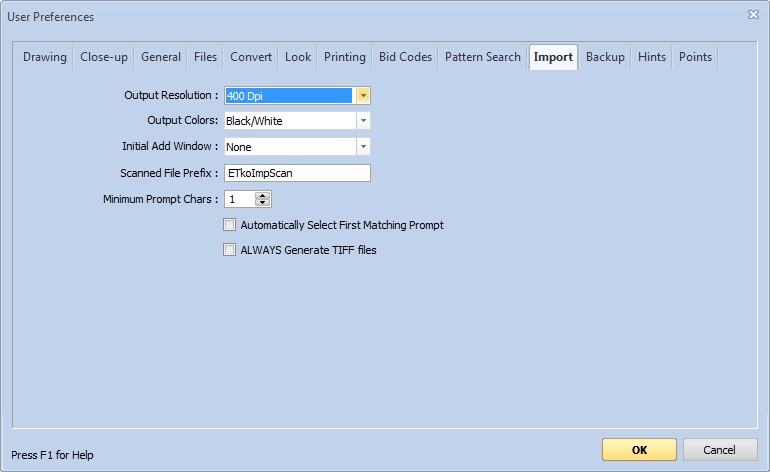
Figure 13: The User Preferences Window - Import
This window is used to set various user preferences for Drawing Import.
Output Resolution : - This setting determines the output resolution for drawings that are not already raster images (bitmaps) such as PDF files. For raster images, we use the same resolution as the original drawing.
Output Colors : - There are three output color schemes available:
Initial Add Window : - This setting determines which window (if any) is displayed to add drawings to the Drawing List Window. The import process displays the Output Folder/Project Selection Window; then the Filename Mapping Window then the Drawing List Window. Based on this setting, an initial window can be displayed over the drawing list window automatically. The options are:
Scanned File Prefix : - When drawings are imported from a drawing scanner, they are placed directly in the destination folder, then later renamed. This prefix will be used as the start of the name of the scanned drawings. So if this prefix were "ETkoImpScan", the scanned drawings would be named "ETkoImpScan0001.tif", "ETkoImpScan0002.tif", etc..
Minimum Prompt Chars : - Terms such as "Architectural", "Electrical Details" or "Elevation" that occur frequently in drawing names can be set up as prompts using the Prompt List Window. These prompts can then be quickly inserted into input fields in the Drawing Conversion Window. This setting determines the number of matching characters needed before a prompt is displayed. For example, if this setting were 2, then typing "e" wouldn't display any prompts but typing "el"r would display the prompts shown in figure 2.
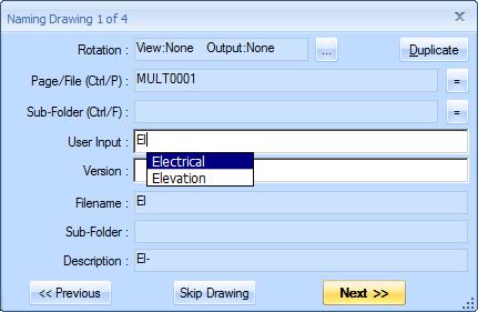
Figure 14: Drawing Conversion Window with Prompting
Automatically Select First Matching Prompt - This preference controls prompt selection when the prompt list is displayed as shown in figure 2. In that figure, the first row is selected and displayed with a blue background.
If this preference is checked, the first row in the prompt window is selected automatically. If you want to use this prompt, simply press the "Tab" or "Enter" key. If you DON'T want the selected prompt but wish to use the text you have entered, you must press the "Esc" or "Escape" key to clear the selection. Then press the "Tab" or "Enter" key. Pressing the "Esc" or "Escape" key is only necessary when you wish to use the text you have entered without typing anything more. If you type more and no matching prompt exists for what you type, the prompt list will disappear.
If this preference is NOT checked, the prompt list will appear with no row selected. To select a row, simply press the down arrow key and the first row will be selected.
ALWAYS Generate TIFF Files - If this preference is checked, TIFF files will be generated for all input file types. If it is NOT checked, PDF input files will generate PDF output files while TIFF files will be generated for all other input file types. If you convert PDF files to TIFF files to improve performance, you should check this preference.
Points Preferences
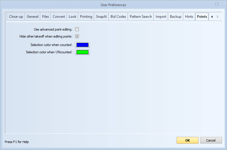
Figure 15: The User Preferences Window - Points
Use advanced point editing : - If this preference is checked, you will have all the power of Advanced Point Editing. If it is unchecked you will only have the traditional simple point editing.
Hide other takeoff when editing - If this is checked, when you start editing points of a measurement, all other measurments will be hidden. This makes it easier to select individual points.
Selection Color when counted - This button displays the color of the point highlight when a point is selected and the point is counted. Press the button to change the color.
Selection Color when UNcounted - This button displays the color of the point highlight when a point is selected and the point is NOT counted. Press the button to change the color.
Buttons Outside the Tabbed Area
OK - Press this button to finish setting the user preferences and return to the Main Window.
Cancel - Press this button to cancel setting the user preferences, discard all changes made and return to the Main Window.
Help - Press this button to display information about how to use the User Preferences Window.