
Release 2.3 Enhancements
Extensions
Extensions allow user input and calculations to be added to individual measurements. For example, a "Wall Area" extension would allow the user to enter the wall height then calculate the wall area as the measurement length multiplied by that height. Extensions are not available in the Basic viewer. For more information see:
- Extensions Overview
- Standard Extension Maintenance
- Measurement Extension Maintenance
- Extension Column in the Measurement List
- Selecting an Extension for a Quantity Worksheet Item
- Extension Column in the Quantity Worksheet
There are two extensions that expand the capabilities above to help layout material to be applied to an area. The Grid Extension can be used to layout rectangular material such as wall or ceiling tiles. The Roll Extension can be used to layout rolled material such as carpet or tar paper.
Bid Codes
Bid Codes are used to organize measurements. They can also be used to facilitate the transfer of information to Excel and other estimating applications. Standard bid codes are pre-defined or commonly used bid codes that can be set up in advance or copied and pasted from another application. They can then be quickly assigned to a standard trace, a measurement trace or a quantity worksheet item.
Bid codes can be displayed in a column in the measurement list and the quantity worksheet. From there they can be transferred to other applications along with the other columns. For more information see:
- Standard Bid Code Maintenance
- Selecting a Bid Code for a Trace
- Bid Code Columns in the Measurement List
- Selecting a Bid Code for a Quantity Worksheet Item
- Bid Code Columns in the Quantity Worksheet
- Bid Code Lookup Window
- Bid Code Use in the Excel Add-on
- Configuring Bid Code Preferences
Issue Management
During the takeoff process, issues arise that need to be resolved later. The Issue Management features allow Pro and Premier users to define issues and assign drawings and measurements to them. When working with a planroom that supports collaboration, issues can be sent to other project collaborators as a Request for Information (RFI). For more information see:
Auditing Features
Release 2.3 adds a number of auditing capabilities. For more information see the Auditing Overview
Angle and Pitch display
Have you ever wanted to know the angle or pitch for a roof line or some other line in a drawing? Simply create a measurement that tracks the line. Then right-click on one end of the line and select "Display Angle and Pitch..." from the context menu. The Angle and Pitch Window will be displayed showing the angle and pitch for the lines connected to the point. You can even copy the angle or pitch to the clipboard.
Annotation Enhancements
Multi-segment Line Annotations - Before release 2.3 line annotations were limited to two points. Now you can have as many points as needed with the line going from the first point to the successive points.
Freehand Annotation - A new annotation has been added that allow you to draw freehand lines my holding down the left mouse key and moving the mouse. For more information see the Annotation Toolbar.
Cloud Annotation - A new annotation has been added that allow you to draw a "cloud" around part of a drawing. Simply digitize the points around the area (you don't need to close the area). A cloud will be drawn from the first point through the successive points and back to the first point. For more information see the Annotation Toolbar.
The Control Panel
The Control Panel is a vertical panel that can be displayed on the left side of the Main Window. Different "Controls" can be placed in the panel to provide quick access to functions such as the Bird's-eye view, the drawing list, the layer list, the measurement quantity list and the drawing rotation. For more information see the Control Panel
Extra Drawing Windows
You can now view multiple drawings simultaneously without opening additional copies of the viewer. For more information see Opening Extra Drawing Windows.
Grid Drawing Generation
Grid Drawing Generation is useful when field measurements and sketches must be taken to generate takeoff quantities. The process typically works as follows:
- A rough estimate is made of the size of the area to be sketched.
- In the Dimension Grid Generation Window, select a scale, paper size and grid size large enough for the field area and generate the drawing.
- Print out the generated drawing.
- In the field, use the printed drawing to sketch the actual work to be done.
- Scan the sketch into a TIFF file and add it to the Dimension project.
- Use Dimension to create measurements from the sketch.
For more information see the Grid Drawing Generation Window.
Miscellaneous
Export to Construction Suite... - If you are using UDA's Construction Suite © for estimating or accounting, this option will allow you to generate an Excel file formatted for use by Construction Suite. When you select this option, you will be asked to select a file for the output. Then the project measurements will be exported into that file. The following rules are used when exporting:
- Measurements without Bid Codes are transferred individually with the measurement description used for the name.
- Measurements with a common bid code and data type (area, length, etc.) are combined into a single row. The description will be the description from the Standard Bid Code. If the bid code doesn't match a standard bid code, the description will be blank.
Move/Copy Measurements and Annotations - You can now select and move or copy measurements and annotations. Copying measurements can be useful in several situations:
- When a footing is repeated many times in a drawing, you can create a measurement for the first footing, setting the trace, etc. For the rest of the footings, set Move/Copy mode, hold down the Ctrl key and drag the existing footing to the next one.
- Pro users often need to use different dimensions (such as area and perimeter) for a single complex measurement and have both dimensions appear in the measurement list. Now you can make a copy (moving it slightly if desired) then change the trace for the copied measurement to show the second dimension.
For more information see the Measurement Toolbar.
Organize Traces in a Tree - Selecting traces from a list works well when you have only a few traces. But when you have hundreds of traces it's cumbersome. Now you can organize standard traces in a hierarchical tree and select them using that tree.
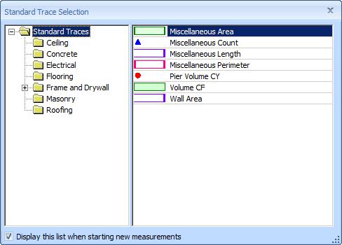
Figure 1: Selecting Traces from a Tree
For more information see the Organizing Traces in a Tree.
Purge Unused Drawings - This option allows unused drawings to be deleted from a project. It can be used in several scenarios:
- When initially evaluating a project, many drawings may be viewed and automatically added to the project. But these drawings (once reviewed) are no longer needed. The purge allows them to be quickly removed from the project.
- Mistakes or timing errors in project importing, exporting or file renaming can cause filenames or paths in the project to differ from the actual filenames and paths. In some cases, only a few of many drawings have activity (measurements, scales, etc.). The purge can remove all the drawings that don't have activity. The remaining drawings can be renamed manually. Then a drawing scan can be used to re-add the other drawings with their correct filenames.
Project Export and Zip - This option allows you to export the project information, then zip up that information plus drawing files into a single zip file. The zip file can then be transferred to another computer and imported (via Dimension) to re-create the project as well as the drawing files. For more information see The Project Export and Purge Wizard.
Save and Reload Column Configurations - In the Measurement List and the Quantity Worksheet, you will probably want to configure the columns differently for different purposes. For example, you might have one configuration for reviewing information and another for transferring information to Excel or other applications. Now you can right-click in the column heading and use menu options to save a configuration, re-load a saved configuration or delete an obsolete configuration.
Current View Remembered - When a measurement or annotation is assigned to a quantity worksheet item or an issue, the current view (zoom and scroll) for that assignment is remembered. If you later click or double-click on the assignment to view the measurement or annotation, the drawing view will be changed to match the view at the time of the assignment.
Export and Import Standards - For multiple users in an organization, there is a need to use a common set of standard layers, traces, scales, bid codes and extensions. Exporting standards allows one user to select different standards and export them to a file. This file can then be sent to other users. The recipients can then Import the standards. During the import, the user may select which standards to import.
Export to Construction Suite - If you are using UDA's Construction Suite © for estimating or accounting, you can set up bid codes to match theirs and automatically transfer information. See the Main Menu for more information.
Main Window Shortcut Keys - In the Main Window Shortcut keys have been added for most commonly used operations. The shortcut keys have also been simplified to minimize use of the Shift and Ctrl keys.
Main Window Cursors - In the Main Window different cursors are displayed to indicate what step the next mouse action will perform.
Quantity Worksheet Shortcut Keys - In the Quantity Worksheet, pressing the Insert key is equivalent to pressing the Add Branch button. Pressing the Delete key is equivalent to pressing the Delete Branch button.
Select Measurements and Annotations from List - When multiple measurements or annotations are overlaid it is difficult to select an individual measurement just using the mouse cursor. The Main Window Context Menu now has an option to "Select from List...". If you select this option, the Measurement Selection Window will display a list of the measurements and annotations that are close to the mouse cursor. From this list you can select a single measurement or annotation.
Annotation Settings Kept by Annotation Type - When you create a new annotation, the annotation's settings (color, font, line thickness, etc.) will be initialized to the settings you last used for that type of annotation (line, text, cloud, etc.). Before we reused the settings used for any type of annotation.
Length Tooltip for Line Annotations - To verify the scale you can create a line annotation over a dimension specified in the drawing. After you set the scale, pause the mouse over the annotation. Tooltips for line annotations now include the length. You can validate the scale by comparing the tooltip length to the specified dimension.
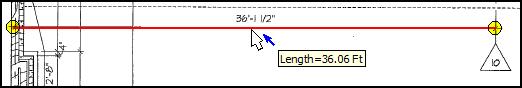
Figure 2: Line Annotation over Specified Dimension
with Tooltip Displayed
