
Grid Drawing Generation Window
This window is the first step in generating a drawing file with a grid of a certain size. This is useful when field measurements and sketches must be taken to generate takeoff quantities. The process typically works as follows:
- A rough estimate is made of the size of the area to be sketched.
- In the Dimension Grid Generation Window, select a scale, paper size and grid size large enough for the field area and generate the drawing.
- Print out the generated drawing.
- In the field, use the printed drawing to sketch the actual work to be done.
- Scan the sketch into a TIFF file and add it to the Dimension project.
- Use Dimension to create measurements from the sketch.
To generate a grid drawing, click on the Drawing Tab / Generate Grid Drawing button. The Grid Drawing Generation window will be displayed.
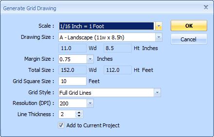
Figure 1: The Grid Drawing Generation Window
Scale : - The combo box has a list of all your Dimension standard scales. Select one of the scales for the drawing you're going to generate. If the scale you want isn't in the list, you can add standard scales using the Standard Scale List. You must select a scale to enable most of the following controls.
Note: The scale will be displayed in the bottom-right-hand corner of the generated drawing.
Drawing Size : - This combo box has a list of the common construction drawing sizes. For each size there is a "Portrait" and "Landscape" version. There is also a "Custom" option to specify a non-standard size.
Drawing Size Wd and Ht : - If you selected a standard drawing size, the width and height of that size will be displayed in the edit boxes and can't be changed. If you selected the "Custom" drawing size, you must specify the width and height of the drawing in these boxes. You can use up to two decimal places.
Margin Size : - This combo box has a list of the different margin sizes. This will be the distance from the edge of the drawing to the edge of the grid on all four sides.
Total Size : - Once you have specified the scale, drawing size and margin size, this will display the total size of the grid in actual units. You can use these values to make sure the grid will be large enough for the area to be sketched.
Grid Square Size : - Enter the desired grid size in actual (field) units. You can use up to two decimal places.
Note: The grid size will be displayed in the bottom-left-hand corner of the generated drawing.
Grid Style : - This combo box contains the three different styles available for the grid:
- Full Grid Lines - Grid lines will extend from the top to the bottom and from the left to the right edges of the drawing.
- Small Horz/Vert Crosses - Each intersection point of the grid will be marked with a small horizontal/vertical cross (like a plus sign).
- Small Diagonal Crosses - Each intersection point of the grid will be marked with a small diagonal cross (like the letter "X").
Resolution (DPI) : - This combo box has a list of different drawing resolutions from 200 to 1200. Higher resolutions have more clarity but generate a larger drawing file. For simple grids, high resolution is usually unnecessary. A resolution or 200 to 400 DPI is usually fine.
Line Thickness : - This control specifies the width of the grid lines and the drawing frame. We recommend a minimal line thickness of 2 for 200 DPI drawings, 300
Add to Current Project - If you are viewing a Dimension project when you invoke the Grid Generation Window, this checkbox will be enabled. If you check it, the generated drawing will be added to the project and the drawing will be opened after it is generated.
OK - When you have completed all the information for the drawing, press this button to generate the drawing. You will be prompted to specify a folder and filename for the drawing using the standard Windows File Save Dialog.
Cancel - Press this button to exit the Grid Drawing Generation Window without generating a drawing.