
Drawing Scale Edit Window
This window is used to review or set the scale for a drawing. This window is invoked from the Main Menu's "Options/Set Drawing Scale" option or from the Default Scale Window.
Note: You can scroll and zoom the drawing while you are setting the drawing scale
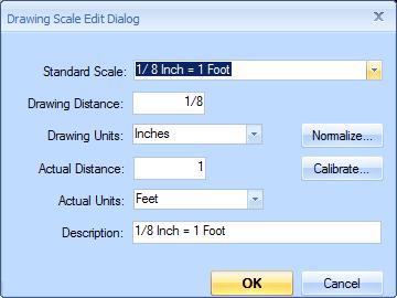
Figure 1: The Drawing Scale Edit Window
Standard Scale - To use a standard scale for the drawing (or start with a standard scale and modify it), press the down-arrow button and select a scale from the list.
Drawing Distance - Enter the scale's distance on the drawing. You can enter this as a fraction if desired.
Drawing Units - Select the unit of measure for the drawing distance.
Actual Distance - Enter the scale's actual distance. You can enter this as feet and inches if desired (such as "5-2" or "5-2 1/2"). Be sure to leave a space between the inches and the fraction.
Actual Units - Select the unit of measure for the actual distance.
Description - The description of the scale is displayed in the Measurement Toolbar. When first defining the drawing scale, you can leave this blank and Dimension will create a description automatically. It you don't like the automatic description, just change it and Dimension will leave it alone.
Normalize... - The same scale can be described in many ways. The scales "1/4 inch = 1 foot", "1 inch = 4 feet" and "2.25 inches = 9 feet" are identical. A "normalized" scale is one where either the drawing distance or the actual distance is one. If you press the Normalize button, Dimension will display a menu containing the three normalized scales. The third option uses 1 foot for the actual distance and sets the drawing distance to the nearest 1/16th of an inch. The percentage the adjusted scale is of the calibrated scale is displayed so you can see how significant the rounding is. Select a menu option to normalize the current scale or press the Escape key to keep the non-normalized scale.
Calibrate... - In some cases, the drawing scale may not be available, but one or more dimensions are specified on the drawing. In this case, you can specify the scale by "Calibrating" it. Press this button to start the calibration process (see Calibrating Scales).
OK - Press this button to finish setting the drawing scale and return to the Main Window.
Cancel - Press this button to cancel setting the drawing scale and return to the Main Window.
Validating the Scale
WARNING: The Scale displayed on the drawing is not necessarily the scale of the image. The image may have been generated at a different size than the original drawing. We have also seen cases where architects use a template for a drawing and forget to change the scale. WE STRONGLY ENCOURAGE YOU TO VALIDATE ANY SCALE YOU SET TO THE SCALE DISPLAYED ON THE DRAWING.
One way to validate the scale is to create a measurement or a line annotation or a dimension annotation along a specified dimension in the drawing. The annotation may be preferable because it won't appear in the measurement list. If you pause the mouse over the measurement or annotation, the length will be displayed as a tool tip. Make sure that length matches the dimension specified in the drawing.
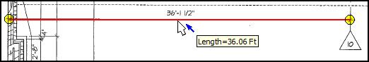
Figure 2: Line Annotation over Specified Dimension
with Tooltip Displayed
Not to Scale Drawings
Some drawings (such as isometric drawings) are Not To Scale (NTS). You can still count the points and specify the length for measurements on NTS drawings. The first step is to identify the drawing as NTS. You can do this by selecting "Not to Scale" from the Standard Scale drop-down list above. Then select the Actual Units. For more information see Not To Scale Drawings.
Not To Scale is only available in the Premer version of Dimension.