
Ribbon Bar Home Tab
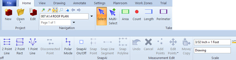
The Home tab of the Ribbon Bar is intended for use when navigating through projects and drawings and doing simple measurements.
Project

Create New Project
Press this button to create a new project. The folder for
the project should exist before you create the project. Ideally,
you should have the drawing files for the project on your system when you
create the project. That's not required but there isn't much you
can do with a project that has no drawings.
When you press this button, a standard Windows Folder Selection dialog
will appear. Select the project folder and press OK. The
Project Properties Window will
then appear, allowing you to define the properties for the project.

Edit
Press this button to edit properties for the current project. The Project Properties Window will appear.

Open
Press the icon button to view a list of Dimension projects. You can navigate from project to project by pressing this button and selecting from the alphabetized list. You can drag the edge of the list window to change its width or height.
Pressing the drop-down button beneath the icon displays three options:
Open Project via List
This is the same as pressing the icon button
Open Project via Tree
The project tree works much like the project list. You can select this option and select a project. The difference is that instead of an alphabetized list, the tree button displays a tree of project organized by the project folders. You can drag the edge of the tree window to change its width or height.
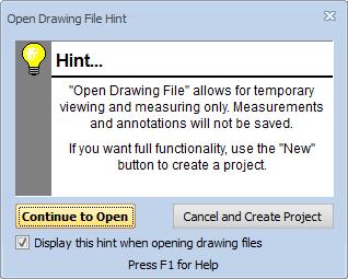
Open Drawing File
Open a drawing file. This is typically used to open a file that isn't part of a project, but it can be used to open a project drawing. If you are working within a project, it's much easier to open drawings using the Drawing List. Optionally a hint window will be displayed.
For more information on using projects see the Project Management Overview.
Navigation

Zoom In
Press this button to zoom in on the drawing (see more detail). Each time you press the button, the drawing is enlarged by the zoom percentage. The zoom percentage can be set using the User Preferences Window.

Zoom Out
Press this button to zoom out on the drawing (see less detail but more of the drawing). Each time you press the button, the drawing is reduced by the zoom percentage. The zoom percentage can be set using the User Preferences Window. This button will be disabled when the drawing is viewed at full size.


Zoom Rectangle
Press this button to zoom in on a particular area of the drawing. After pressing the button (it will stay down), click-down on one corner of the area, drag the mouse to the opposite corner and release the button. As you drag, a rectangle will be displayed to show the zoom rectangle.
You can also zoom out by rolling the wheel backwards.

Bird's Eye Window
Press this button to display the Bird's Eye Window This window shows the entire drawing and highlights the area currently displayed. You can scroll the drawing by clicking and or dragging in the window

Previous
As you navigate from drawing to drawing or view to view within a project, Dimension keeps a historical record. Press this button to go back to the previous view or drawing. You can press the button multiple times to go back multiple steps. The navigation history includes the following types of navigation:
- Selecting a different drawing
- Following a hyperlink to another view or drawing
- Switching drawings by double-clicking on a measurement or annotation in the Quantity Worksheet Window

Next
After you use the Previous button to go back one or more steps, you can go forward again by pressing this button. Navigating by any other method eliminates the "forward" history and the button will be disabled.

Current Drawing
This control shows the current drawing. The picture shown here doesn't show the full width. It will be blank if no drawing is displayed.

Drawing List
Press this button to view a list of the drawings for the current project. You can navigate from drawing to drawing by pressing this button and selecting from the alphabetized list. Each row in the list has a symbol indicating the drawing status. See Drawing Status below for a description of the symbols. You can drag the edge of the list window to change its width or height. Shortcut: You can switch to the next drawing or the previous drawing in the alphabetized list by pressing the "Page Down" or "Page Up" key.

Page Number
For multi-page drawings, this control can be used to navigate
through the pages. You can use the drop-down list to select a
page or simply enter the desired page number.
You can drag the edge of the list window to change its width or height.
Takeoff

Select Measurement or Annotation
To select a measurement or annotation, press this button then click on the desired measurement or annotation. The selected measurement or annotation will display yellow circular selection symbols for all points. This button will look like it is "down" whenever you are in select mode. Shortcut: You can switch to select mode by pressing the "Enter" key or the "S" key.

Select Multiple Measurements and/or Annotations
To select multiple measurements and/or annotations, press this button then click on the
desired measurements or annotations. If you click on a measurement that is
already selected, it will be de-selected.
You can also select by dragging a rectangle around the desired measurements
and/or annotations. Press the left mouse button down on one corner of the selection
rectangle, drag the mouse to the opposite corner then release the left mouse button.
Any measurements or annotations that fall entirely inside the rectangle that were
not previously selected will be selected. If everything inside the rectangle
was already selected, they will be de-selected.
The selected measurements and/or annotations
will display yellow circular selection symbols for all points.
This button will look like it is "down" whenever you are in multiple-select mode.
This feature is available with Pro-Plus, Advanced,
Premier and the Drawing Compare Add-on.

Add New Measurement
To add a new measurement, press this button then begin clicking
on the points in the measurement.
In the Basic Viewer, measurements are not stored so starting
a new measurement will erase any measurement you were previously working on.
Shortcut: You can add a new measurement by holding the
Control key down and pressing the "A" key or the "N" key.
You can complete the measurement by changing to Select mode. This
can be done by pressing the Select button in the toolbar,
pressing the Enter key or pressing the "S" key.
If "Show trace buttons in ribbon bar" is checked in the "Look" tab
of the User Preferences,
this button will be replace by the Area, Count, Length and
Perimeter buttons described below.

Area
To add a new Area measurement, press this button then begin clicking
on the points in the measurement.
In the Basic Viewer, measurements are not stored so starting
a new measurement will erase any measurement you were previously working on.
You can complete the measurement by changing to Select mode. This
can be done by pressing the Select button in the toolbar,
pressing the Enter key or pressing the "S" key.

Count
To add a new Count measurement, press this button then begin clicking
on the points in the measurement.
In the Basic Viewer, measurements are not stored so starting
a new measurement will erase any measurement you were previously working on.
You can complete the measurement by changing to Select mode. This
can be done by pressing the Select button in the toolbar,
pressing the Enter key or pressing the "S" key.

Length
To add a new Length measurement, press this button then begin clicking
on the points in the measurement.
In the Basic Viewer, measurements are not stored so starting
a new measurement will erase any measurement you were previously working on.
You can complete the measurement by changing to Select mode. This
can be done by pressing the Select button in the toolbar,
pressing the Enter key or pressing the "S" key.

Perimeter
To add a new Perimeter measurement, press this button then begin clicking
on the points in the measurement.
In the Basic Viewer, measurements are not stored so starting
a new measurement will erase any measurement you were previously working on.
You can complete the measurement by changing to Select mode. This
can be done by pressing the Select button in the toolbar,
pressing the Enter key or pressing the "S" key.

Two Point Line Takeoff
Some measurements consist of a series of many disconnected line segments
of two points each. These can be measured using the Disconnected Points button
described above, but Dimension supports a special mode that makes
it even easier. To use this mode; start a new measurement,
add 1 point then press this button.
When you press this button, it will look like it is "down"
to show that you are in Two Point Line Takeoff mode.
As you add points, disconnected line segments are created automatically.
Point 1 and point 2 form the first segment, points 3 and 4 form a second
disconnected segment, points 5 and 6 form a third segment, etc.
You can end this mode of takeoff by pressing the
Select Measurement or Annotation,,
Add New Measurement,
Add Points to Measurement,
Edit Measurement Points,
Add Disconnected Point or
Two Point Rectangle Takeoff button.
This button is enabled only in the Pro, Pro-Plus, Advanced and Premier Viewers.
Note: If you select an existing measurement and press the Two Point Line button, it is assumed that you want to start a NEW measurement adding points in that mode. To add two point lines to an existing measurement, press the Add Points button then press the Two Point Line button.

Two Point Rectangle Takeoff
This is similar to the Two Point Line Takeoff mode
described above, but it's used for measurements that consist of
a series of rectangles. Each rectangle is identified by clicking on
two opposite corners. To use this mode; start a new measurement,
add 1 point then press this button.
When you press this button, it will look like it is "down"
to show that you are in Two Point Rectangle Takeoff mode.
As you add points, disconnected rectangles are created automatically.
Point 1 and point 2 are used to form the first rectangle,
points 3 and 4 to form a second disconnected rectangle,
points 5 and 6 to form a third rectangle, etc.
The first point you click becomes the first point of the rectangle.
The second point you click becomes the third point of the rectangle.
The second and fourth points are generated automatically.
If the second point is to the right of the first point, the points
are arranged in a clockwise direction and the rectangle's area will be positive.
If the second point is to the left of the first point, the points
are arranged in a counter-clockwise direction and the rectangle's area will be negative.
Negative areas can be used for cutouts such as windows in a wall.
You can end this mode of takeoff by pressing the
Select Measurement or Annotation,,
Add New Measurement,
Add Points to Measurement,
Edit Measurement Points,
Add Disconnected Point or
Two Point Line Takeoff button.
This button is enabled only in the Pro, Pro-Plus, Advanced and Premier Viewers.
Note: If you select an existing measurement and press the Two Point Rectangle button, it is assumed that you want to start a NEW measurement adding points in that mode. To add two point rectangles to an existing measurement, press the Add Points button then press the Two Point Rectangle button.

One Point Line Takeoff
Some trades need to easily create multiple straight lines from a common hub point to multiple end points. This is useful in low voltage wiring where the wires can go in straight lines:
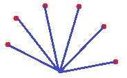
One point lines are created via the following steps:
- In the User Preferences Look tab make sure "Show 1 point line in ribbon bar" is checked.
- Click to create the hub point.
- Select One Point Lines.
- Each time you click on a point, it will create a disconnected group of two points, one at the hub and one where they clicked.
Many times, the lines are being drawn to points that are part of an existing count measurement. For example you might count all the security cameras for a floor then want to digitize wire runs from a control center to each camera. You can do that as follows:
- Create the count measurement first (for the cameras).
- Start a new measurement for the wire runs.
- Click to create the hub point.
- Select One Point Lines.
- Right-click on the camera measurement. Because we're in One Point Line mode, and you right-click on a point for an existing measurement, the context menu will include an option to `Draw lines to all "XXXX" points" Where XXXX is the name of the measurement you right-clicked.
- Select that option and one point lines will be drawn from the hub to all the points in the selected measurement.
Note: If you select an existing measurement and press the One Point Line button, it is assumed that you want to start a NEW measurement adding points in that mode. To add one point lines to an existing measurement, press the Add Points button then press the One Point Line button.

To create two disconnected groups, first add the points in the first group, press this button then add the first point of the second group. When you press this button, it will look like it is "down" to show that the next point will be disconnected. When you add the next point, this button will pop "up" and the Add Points to Measurement button will be down as you add more points to the second group. A measurement can have an unlimited number of groups.
Shortcut: You can also add a disconnected point by pressing the G key before you click the first point in the second group.
This button will be disabled in the Basic Viewer.

Toggle Polar Mode On/Off
When adding points in polar mode, the point is forced to fall on a line
that is a multiple of 90 degrees from the previous point.
This is most commonly used to create horizontal or vertical lines.
It can also works for lines of various angles. You can select
the desired angles in the
User Preferences Window.
Note: You can temporarily toggle polar mode
by holding down the Ctrl key.
Note: There is a user preference to disable polar
mode when creating measurements with a Count data type.
See the "Drawing" tab of the
User Preferences Window.

Snap Point
Press this button to invoke Snap Point Mode . SnapSnap to Point mode detects points in vector PDF files. When the user is in Snap to Point Mode, a sense indicator appears by the cursor. This option is only available with the Premier Viewer.

Snap Line
Press this button to invoke Snap Line Mode . Snap to Line mode detects lines in vector PDF files. When the user is in Snap to Line Mode, a sense indicator appears by the cursor. This option is only available with the Premier Viewer.

Snap Polyline
Press this button to invoke Snap Polyline Mode . Polylines are a set of logically connected lines. Snap to Polyline works the same way as Snap to Line except that if the closest line is a polyline, all points in the polyline are added to the measurement. This option is only available with the Premier Viewer.
Measurement Edit

Undo Last Change
To undo the last change made to a measurement, simply press this button. You can press the button multiple times to undo multiple changes. Undo works on the following changes:
- Adding points (connected or disconnected)
- Editing points
- Changing the trace (by editing or selection)
- Editing the description

Cancel Changes to Measurement
Press this button to cancel all changes to the measurement you're working on.
If you are adding a new measurement, it will be deleted. If you are
making changes to an existing measurement, all changes made since
you selected it will be reversed.
Shortcut: You can also cancel all changes to the measurement
by pressing the Escape key.

Add Points to Measurement
This button will look like it is "down" whenever you are in
point adding mode. In this mode, each time you click on
the drawing, the point is added to the current measurement.
This mode is set automatically when you press the
Add New Measurement button.
When adding points, you can hold down the "Ctrl" key while
clicking to force the line from the previous point to the new
point to be horizontal or vertical.
While adding points, you can automatically generate arcs
or circles. For more information, see
Taking off Arcs and Circles.

Edit Measurement Points
This button will look like it is "down" whenever you are in point editing Mode. There are two different point editing styles: Regular and Advanced. If you have selected Advanced Point Editing in the User Preferences Window, pressing the top of this button will invoke all the Advanced Point Editing features. Otherwise you will have the regular point editing features described below.
If you press the bottom part of the button you will see a menu to select either Regular or Advanced point editing, regardless of your user preference.
With regular point editing, you can move points, insert points or delete points:
- To move a point, press the left mouse button down on the point. Holding the button down, drag the point to the desired location then release the button.
- To insert a point (between two existing points), press the left mouse button down on the line between the points (away from the points). Holding the button down, drag the new point to the desired location then release the button.
This button will be disabled in the Basic Viewer.

Move or Copy Annotations and/or Measurements
To move annotations and measurements, first select the annotations and measurements you wish to move. Then press this button. This button will look like it is "down" whenever you are in move mode. Click down on one of the selected objects then drag it to the desired position. To COPY, hold the Ctrl key down while you click down with the mouse button. When copying, Quantity Worksheet assignments will NOT be copied. But if Auto-assign is on in the Worksheet Assignment Control, new assignments will be created. To terminate move mode, press the Select Measurement or Annotation Button
Scale

Measurement Scale
The scale is displayed at the right end of the home tab.
The upper display is the current scale. The lower display
is the scope of the scale. This will say "Drawing" in
most cases but if you select a measurement that is inside
a detail scale it will display the name of that detail scale.
To set or change the scale, press the button to the right of the upper display.
The Drawing Scale Edit Window will
be displayed to set or change the drawing scale.